
How to Choose a CNC Press Brake: A 14-Point Checklist
Most press brake mistakes are made before the quotation is signed. A buyer picks a tonnage that is too low, or too high and overpriced. A machine arrives that has enough force but cannot physically accept the part, because a return flange hits the side frame on the second bend. Or the machine is right and the tooling is wrong, so every job needs a workaround.
Choosing a CNC press brake is not a single decision. It is a sequence of decisions, and the sequence matters: material and part geometry first, then the specifications that decide whether the part physically fits, and only then drive type, tooling, control, supplier and price.
This guide walks that sequence in order. Each section ends with the question you should put to your supplier.
1. Start with the part, not the machine
1.1 Materials and thickness range
Write down every material you bend today and expect to bend in the next three years, with the thickness range for each:
Do not size the machine on your average job. Size on the heaviest part you are contractually willing to accept, then check that the average job still runs economically on the same machine.
1.2 Bend geometry
Three numbers per part:
- Bend angle and tolerance. A 90° bracket with ±1° tolerance and a 90° enclosure panel with ±0.25° tolerance are not the same requirement, and they do not point to the same machine.
- Bend length. The longest single bend, not the total bend length of the part.
- Inside radius. This is the number most often missing from an inquiry, and it determines the die opening you must use.
1.3 Throughput and growth
Estimate bends per hour and bends per shift for your busiest product. Then ask what happens if that volume doubles. A machine that is 20% cheaper but needs a tooling change on every second job will cost more in two years than the machine you avoided buying.
2. Drive type: hydraulic, electro-hydraulic servo, or all-electric
The common framing of “hydraulic versus servo” hides the fact that there are three drive architectures, and the middle one is what most CNC press brakes sold today actually use.
2.1 Hydraulic press brake
A hydraulic cylinder or cylinders drive the ram. A pump supplies oil pressure, and valves control flow.
- Strength and range. The most capable architecture at high tonnage and long bending lengths. Well suited to thick plate.
- Stability. Hydraulic pressure is smooth and consistent, which gives stable, repeatable bends even on heavy material.
- Cost. Generally the lowest purchase price of the three, which is why it remains dominant in heavy plate work.
- The trade-offs. Oil needs filtering, monitoring and periodic replacement; seals and hoses age; oil temperature drifts under continuous duty and can shift accuracy; the pump draws power continuously whether or not the ram is moving. Older or poorly maintained machines leak.
2.2 Electro-hydraulic servo press brake
Still hydraulic, but the pump is driven by a servo motor and the ram position is closed-loop controlled, in most cases with a proportional or servo valve and a position/ pressure sensor on each side.
- Synchronisation. Both cylinders are measured and corrected in real time, so the ram stays parallel across the full bend length. This is the main reason this architecture dominates precision sheet metal work.
- Precision. Typically tighter angular tolerance than a conventional hydraulic machine, and less drift as oil temperature changes.
- Energy. A servo-driven pump draws power mainly when it is doing work, rather than continuously, so consumption is lower than a conventional hydraulic machine.
- Cost and maintenance. Priced between the other two. Still has oil, filters and seals to service.
If your inquiry says “CNC press brake” and lists a hydraulic cylinder with servo control, this is almost certainly what you are being quoted.
2.3 All-electric servo press brake
Servo motors drive the ram directly, usually through ball screws or belts. There is no hydraulic oil in the force path.
- Energy. An electric machine draws power only while the motor is moving. Suppliers commonly quote 50–70% lower energy consumption than a conventional hydraulic machine; the actual figure depends heavily on your duty cycle, so treat it as a range and verify against your own shift pattern, not as a fixed number.
- Maintenance and cleanliness. No oil, no filters, no hydraulic leak risk. Fewer consumables and fewer contamination problems around sensitive parts.
- Speed. Fast positioning and short cycle times, which matters in high-mix, small-batch work where setup and approach time dominate.
- Noise and environment. Quieter operation, and no oil mist, so it suits clean assembly areas.
- Limits. Typically offered at lower tonnage than hydraulic machines, which makes it a thin-to-medium sheet solution rather than a thick-plate solution. High tonnage is still hydraulic territory.
2.4 Comparison
Ask your supplier: which architecture is this quotation, and is the ram synchronised in a closed loop on both sides?
3. The five specifications that decide whether the part fits
Tonnage and bending length are the two specifications every buyer checks. They are also not sufficient. A machine can have more than enough force and still be unable to make your part, because the formed part collides with the machine before the bend is complete.
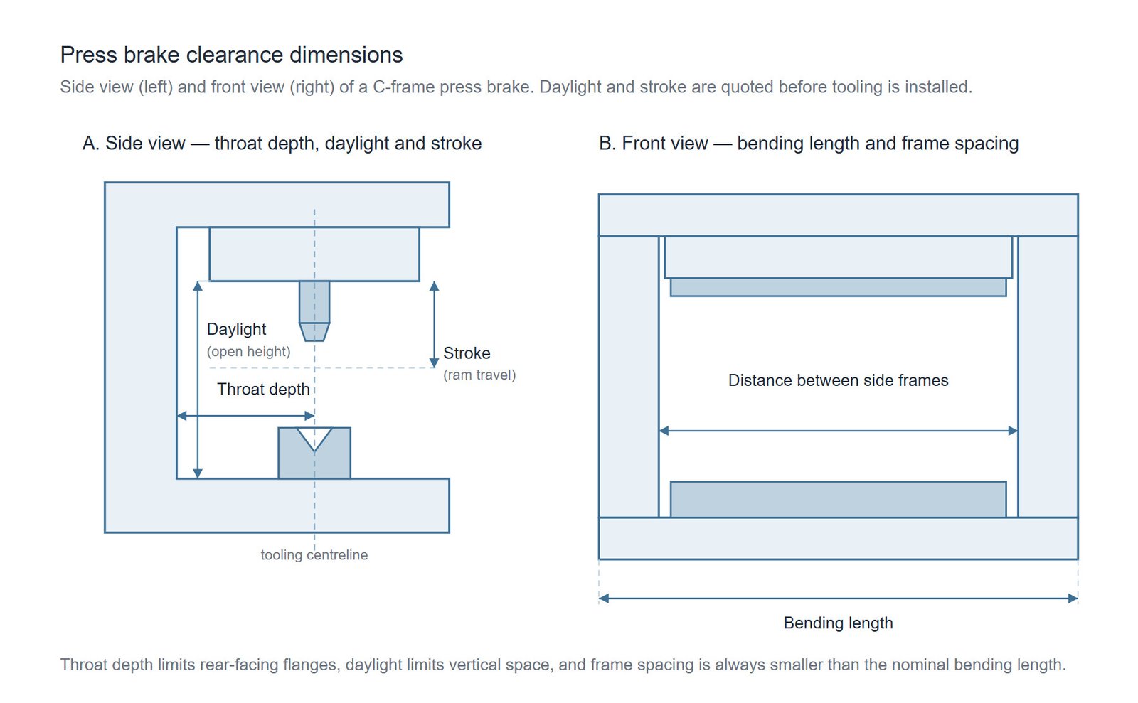
The five numbers to collect are tonnage, bending length, distance between side frames, throat depth, and daylight and stroke. Tonnage and length decide whether the machine can make the bend. The other three decide whether the part can physically pass through the tool and the frame.
3.1 Tonnage
Tonnage is the force the machine can apply. For a 90° air bend in mild steel, the industry-standard estimate is:
P=650×S2×LV
where P is the required force in kN, S is material thickness in mm, L is bend length in metres, and V is the V-die opening in mm. The 650 coefficient is calibrated for mild steel at a tensile strength around 450 N/mm², so it must be adjusted for other materials.
Two rules to apply on top of the formula:
- Do not plan to use more than about 80% of rated tonnage. The remaining margin absorbs material variation and protects the frame and tooling.
- Sizing is dominated by thickness, not length. Because force scales with S2, going from 3 mm to 6 mm is roughly a fourfold increase in force, while halving the bend length only halves it. This is why a thin-plate shop rarely needs a large machine, and why plate work jumps to a different class of machine very quickly.
If you want the full treatment of how tonnage interacts with pressure setting, die opening and material factors, that is covered separately in our guide to press brake pressure adjustment.
3.2 Bending length and distance between side frames
Bending length is the nominal bed length, and it must exceed your longest single bend.
Distance between side frames is the usable opening along the machine length, and it is always smaller than the nominal bending length. A machine quoted as 3200 mm may offer considerably less clear space between the frames. If you bend wide panels, this number, not the headline length, decides whether the blank fits.
For a mid-size CNC press brake, typical values sit in the range of a few metres between frames depending on the model; sizes scale roughly with bed length. Always get the exact figure for the specific model you are buying.
3.3 Throat depth
Throat depth is the horizontal distance from the tooling centreline to the back of the side frame opening. It sets how far a sheet, panel or return flange can extend behind the bend line before it hits the frame.
This is the most commonly underestimated specification in press brake selection, because it does not appear in the headline numbers and it cannot be solved by buying more tonnage. If your part needs a 450 mm return and the machine throat is 320 mm, that bend is impossible in that orientation — more force does not help.
Throat depth matters most for:
- Electrical enclosures, cabinet sides and trays, where a formed wall points back toward the frame
- Door frames and long formed profiles
- Any part where the flat area behind the bend line is large
- Robotic or automated bending cells, which need extra clearance for the gripper to swing
Extended-throat and larger-frame machines exist for exactly this reason. Check throat depth before you compare price.
3.4 Daylight and stroke
Daylight, also called open height, is the maximum vertical opening between the ram tool holder and the bed when the ram is fully open. It is normally quoted before tooling is installed.
Stroke is the vertical travel of the ram from the open position toward the closed position.
These two are frequently confused. Daylight controls how much space you have; stroke controls how much movement you have. A machine can have generous daylight and still fail if the punch cannot travel far enough to reach the bend depth with the tooling stack installed.
The vertical space is consumed by everything in the stack:
usable clearance = daylight
                 - punch height
                 - die height
                 - holders, adapters and clamps
                 - material thickness
                 - formed flange height
                 - safe removal clearance
For a standard 80–160 ton C-frame press brake, typical values are in the region of 320–410 mm throat depth and roughly 120–200 mm stroke on basic models, with higher open heights on advanced CNC models. Exact values depend on frame design and tooling system, so treat these as order-of-magnitude checks rather than targets.
Daylight matters most when the part has to enter, rotate and leave the tool opening — deep boxes, tall flanges, hemming and flattening operations, and gooseneck or high tooling that consumes most of the opening before the part is even loaded.
3.5 A working clearance check you can do from the drawing
Before approving any quotation, run these five checks. This is not a substitute for the supplier’s simulation; it is how you catch an obvious mismatch early.
Ask your supplier: for each of our three most difficult parts, please confirm throat depth, daylight, stroke, distance between side frames and part removal, using the tooling you are quoting.
4. Crowning: how you hold accuracy along a long bend
When a press brake applies force in the middle of a long bend, the ram and the bed deflect. The result is a bend that is correct at the ends and shallow in the middle, or the reverse depending on the setup. On short parts nobody notices. On a 3 m part bending 4 mm steel, it becomes the reason a batch is scrapped.
Crowning (also called deflection compensation) is the mechanism that counteracts this. There are several approaches:
This specification is missing from most buyer checklists and from most quotations. If your parts are longer than about one metre and your tolerance is tighter than roughly ±1°, ask whether crowning is included and whether it is manual or CNC-controlled.
Ask your supplier: does this quotation include crowning, is it manual or CNC-controlled, and over what bend length and tonnage range is it specified?
5. Tooling
Tooling is where a correctly sized machine becomes a productive one, or a constant source of workarounds.
5.1 Die opening and minimum flange
Die opening V is normally selected as a multiple of material thickness — commonly in the range of 6 to 8 times the thickness, depending on the required inside radius and the material. A tighter opening reduces the minimum flange you can form but increases required tonnage and can mark the material.
The constraint that catches people out is the minimum flange length. A given V die cannot form a flange shorter than a proportion of its opening — industry guidance puts this at approximately 77% of the die opening. If a design calls for a 6 mm flange, that rules out a wide die regardless of tonnage.
Check your shortest flange against your intended die opening before specifying the machine.
5.2 Punch profile
- Straight punch. Standard, strongest, lowest cost. Suitable when no return flange has to clear the punch.
- Gooseneck punch. Provides clearance so a previously formed flange can pass over the punch. Note that gooseneck punches are generally taller than straight punches, so they consume more daylight — check the vertical clearance, not just the profile.
- Segmented tooling. Lets box and pan parts be removed from the tool set. It also lets you build a custom length instead of buying a full-length tool.
- Special tooling. Hemming, flattening, radius and offset tools each have their own daylight, stroke and tonnage demands.
5.3 Clamping and changeover
Quick clamping systems and hydraulic or pneumatic clamping reduce setup time, which matters more than headline speed in high-mix work. They also consume part of the open height, so they belong in the daylight calculation.
Ask your supplier: which punch and die profiles are included, what tooling stack height do they represent, and what is the shortest flange they support in our material?
6. Control system, back gauge and precision
6.1 Back gauge
The back gauge positions the blank for each bend. Its axis count is a practical measure of capability:
More axes is not automatically better. Match the axis count to your parts. But if you bend parts with different dimensions on the two sides, or parts that need the gauge to move between bends, a 2-axis machine will cost you setup time on every job.
6.2 Accuracy and repeatability
These are two different claims and suppliers often quote only one:
- Positioning accuracy is how close the machine gets to the commanded position.
- Repeatability is how close successive cycles are to each other.
Repeatability is usually the smaller number and the more important one for production, because a machine that is consistently 0.05 mm off can be compensated; a machine that wanders cannot.
Ask for both figures, and ask for the angle tolerance rather than only the linear positioning figure. Angular tolerance on a real part depends on the material, tooling and crowning as much as on the control system.
6.3 CNC and offline programming
A modern control should let you build a bend sequence, simulate it, and check for collisions before the blank is cut. For products with more than three or four bends, offline programming and simulation pay for themselves by preventing scrapped parts.
Ask your supplier: how many back gauge axes, what is the quoted repeatability, and does the control support sequence simulation and collision checking?
7. Safety and compliance
Press brake bending is a high-risk operation. The upper and lower tools close on the operator’s hands, and the pinch point moves during the cycle.
Check that the machine and its quotation include:
- Guarding that suits the cycle. Modern CNC press brakes typically use light curtains or similar presence-sensing devices combined with speed change points, so the ram slows or stops before contact. Older machines with only a two-hand control or a fixed guard offer less protection and slow the operator down.
- Compliance documentation for your market. For the European Union this means CE marking and a declaration of conformity; other markets have their own regimes. Ask for the documents, not just the plate on the machine.
- The standard and performance level the guarding is designed to. Different markets and applications demand different levels. Ask the supplier to state which standard and which performance level the guard circuit is designed and tested to, and have someone in your organisation verify that claim against your local requirement.
- Physical protection against the ram descending during maintenance or tool change, and a documented procedure for isolating stored hydraulic or mechanical energy.
Do not treat safety options as negotiation levers. These are the items that most often get removed to hit a price, and they are the ones that matter most after an accident.
8. How to evaluate the supplier, not the brand
“Choose a well-known brand” is common advice and it is not useful. Brand recognition is a proxy, not a specification, and in any case what determines your outcome over ten years is the specific factory, the specific service arrangement and the specific people who answer the phone.
Evaluate on capability and commitment instead:
Ask your supplier: may we send you our three most difficult parts for a trial bend and a dimensional report before we place the order?
A supplier who says yes to that question is telling you something more useful than any brand list.
9. Total cost of ownership
Purchase price is the smallest number in the decision. Model the following over five years:
A cheap machine with a two-week spare-part lead time can be the most expensive option on this list.
10. Acceptance test before shipment
Do not accept a machine you have not seen make your parts. Specify the acceptance test in the purchase order, not in a conversation.
Have the results written into the acceptance record and signed. This is the document you will rely on if something is wrong three months later.
11. Selection checklist
12. Working with PLSON
If you are working through this list and would like a straight answer on any line, send us the parts rather than the specification. A drawing, a material and a required tolerance tell us more than a tonnage figure, and it lets us check throat depth, daylight, stroke and tooling against the real geometry before we quote.
We would rather tell you that a 100 ton machine will do the job than sell you a 200 ton machine that will not.
Before you operate any press brake, make sure the guarding, the control system and the operating procedure meet the requirements of your market and your own risk assessment. Specifications, tolerances and performance figures quoted in this guide are typical industry values for orientation only; the figures that apply to your order are the ones stated in your quotation and acceptance record. Always follow the manufacturer’s operating and maintenance manual for the specific machine.
[Contact PLSON Engineers →]
📧 Eric@plsonmachine.com
🏭 Haian Industry Park, Jiangsu Province, China