
Press Brake Pressure Adjustment: Mechanics, Optimization and Shop-Floor Practice
Pressure adjustment is one of the core skills in sheet metal fabrication. It decides whether a part forms to the drawing and how long the tooling and the press brake itself will last. During plastic deformation the force has to be controlled the way a surgeon controls a scalpel: enough to produce the intended bend, never enough to overload the die or the machine. What looks like a single number entered on a controller is really applied materials mechanics, machine engineering and process experience working together.
This article covers the mechanics behind the number, how to optimize the parameters, and the shop-floor points that determine whether the setting holds up in production.
1. The mechanics behind the pressure setting
1.1 Hydraulic pressure and material stress are two different quantities
Before going further, one distinction has to be made, because mixing these two up is the most common source of confusion in this subject.
- Hydraulic pressure is the oil pressure inside the cylinder circuit, measured in MPa or bar. It is what the pressure gauge reads and what the operator sets.
- Material stress is the stress inside the bent sheet, also measured in MPa. It is what decides whether the material yields.
They share a unit but they are not the same thing. The bridge between them is force: hydraulic pressure acting on the cylinder piston area produces force (tonnage), and that force produces bending stress in the sheet. So the correct way to reason is:
Hydraulic pressure → cylinder force → bending moment → outer-fiber stress → plastic deformation
This is why the same gauge reading can be correct for one die and dangerous for another. The pressure is only one part of the chain.
1.2 Stress distribution across the bend
During bending, the sheet is loaded in a way that produces a non-uniform stress field:
The bending moment rises as the ram descends. When the stress at the outer fiber reaches the material’s yield strength, that fiber passes from elastic to plastic behaviour. In practice, production bending aims for a margin above yield — commonly cited as outer-fiber stress reaching roughly 1.2–1.5 times the yield strength — so that the whole thickness is carried past the elastic range and the bend is fully formed rather than partly elastic.
Two consequences follow directly from this:
- Anything that raises yield strength raises the required tonnage. Thickness, grade, temper and work hardening all push in the same direction.
- Anything left in the elastic range comes back as springback. The part of the sheet that never reached yield relaxes when the ram retracts, and the bend angle opens up.
1.3 How material grade changes the force
Material selection changes required force for two separate reasons, and it is worth separating them.
Note on stainless steel. A common claim is that stainless needs 20–30% more force than mild steel. That figure is on the low side. The screening factor used in most tonnage charts for austenitic stainless is around 1.5, i.e. roughly +50%. The exact value depends on the grade and condition, so treat any single number as a screening value and confirm against the material certificate and the machine’s own chart.
Note on aluminum. Aluminum needs less force than steel — but it springs back more, because its elastic modulus is roughly one third that of steel (typical handbook values: about 70 GPa for aluminum against about 206 GPa for steel). A lower stiffness means a larger share of the total deformation stays elastic and returns on unloading. This is why aluminum is a material where the force setting is easy but the angle control is hard, and where staged loading and dwell time matter most.
These two effects are independent. Low required force does not mean easy angle control, and the two must not be treated as one property.
1.4 How die geometry changes the force
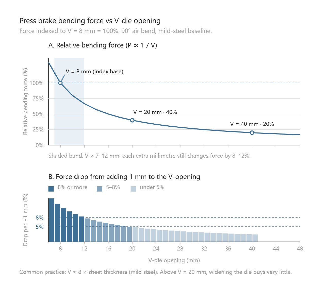
V-die opening. This is the single most powerful variable the operator controls, because the relationship is inversely proportional:
P∝1V
A wider V-opening lowers the force and increases the inside radius; a narrower V-opening raises the force and reduces the minimum flange that can be bent. A rule of thumb in common use is to select the V-opening at about 8 × sheet thickness for mild steel.
Because the relationship is inversely proportional rather than linear, the percentage change per millimetre of opening is not constant. A widely quoted figure of “8–12% less force per extra millimetre of V” is only valid in the small-V range:
The practical lesson: at heavy gauge, where V is large, widening the die by a millimetre buys very little. If force has to come down on a thick part, the die has to change substantially, or the bend length or the process has to change.
Punch tip radius. A larger punch tip radius spreads the contact over a bigger area and lowers the unit pressure, which reduces die marking. It does not, however, follow a simple flat percentage rule for total force — and a claim that going from a 0.5 mm to a 3 mm tip radius raises total force requirement by a fixed 15% should not be relied on. In air bending, the inside radius is largely governed by the V-opening while the punch tip remains smaller than the natural radius; the situation changes in bottoming and coining. The safe approach is to read the required force off the machine’s tonnage chart for the actual forming method, and to treat the punch radius as a surface-quality and minimum-bend-radius decision first.
Minimum bend radius. The punch tip also sets a limit: too tight a tip against a low-ductility material, or against the sheet’s rolling direction, risks cracking. This is a formability constraint, not a force constraint, and it has to be checked before the force is calculated.
1.5 Closed-loop pressure control
A modern CNC press brake closes the loop on pressure rather than letting the operator set it open-loop. The architecture is worth stating precisely, because it is often described inaccurately:
- The servo motor drives the hydraulic pump (electro-hydraulic servo pump), or, on proportional systems, the proportional directional valve is driven by a proportional amplifier. A servo motor does not drive the proportional valve directly.
- A pressure sensor measures actual circuit pressure.
- The controller compares measured pressure with the commanded value and corrects the pump displacement or the valve opening.
This is what allows compensation during the stroke rather than after the part is measured. Two cautions when reading supplier specifications:
- Sensor sampling rate and pressure control accuracy are configuration-dependent. A 1000 Hz sampling rate and a ±0.5 MPa control band are plausible for some models but should be read from the specific model’s datasheet, not assumed as an industry standard.
- Angle deviation figures quoted for a machine are achieved under stated conditions — material, tooling, bend length, temperature. They are not a guarantee for every part.
What the closed loop genuinely delivers is consistency: it removes operator-to-operator variation and compensates for the slow drift of oil temperature and viscosity through a shift.
2. Optimizing the pressure parameters
2.1 The classic tonnage formula and what its coefficient hides
The widely used empirical formula for bending force is:
P=650×S2×LV
where
The coefficient 650 is not a physical constant. It is an empirical number calibrated to a material with a tensile strength of about 450 N/mm², which is why the formula works well for mild steel and progressively less well as the material moves away from that baseline. Everything about the material — grade, temper, work hardening — is hidden inside that single number.
This is the real limitation of the classic formula, and it is worth stating plainly: the formula is not “outdated”, it is calibrated for one material. Used as a mild-steel baseline with a material factor applied on top, it remains a sound screening tool.
A metric equivalent in common use expresses the same relationship per metre of bend:
tonnes-force per metre≈67.4×t2V
for a 90° air bend in mild steel at about 414 N/mm² tensile strength, where t is thickness in mm and V is the die opening in mm.
Cross-check. For 3 mm mild steel over a 2 m bend with a 24 mm V-opening, the 650 formula gives 487.5 kN. The 67.4 formula gives 25.3 tonnes-force per metre, i.e. 50.6 tonnes-force over 2 m, which is about 496 kN. The two agree within roughly 2%. That agreement is the useful part: it confirms both are anchored to the same low-carbon steel baseline, and it means either can be used for screening — provided the material factor is applied on top and the result is checked against the tooling’s own load rating.
A note on the tonnage chart that comes with the machine. Always reconcile the calculated value with the machine manufacturer’s chart and the published linear load rating of the punch, die and holders. A press rated at a high total tonnage may still be limited over a short loaded length or near the end of the bed.
2.2 A material-aware estimate
To make the material explicit rather than hiding it in a coefficient, the formula can be restructured:
P=K×TS×S2×LV×η
The advantage is that substituting a different material no longer requires a lookup in a factor table — the material property is in the equation. Two cautions:
- Do not compare the output of the two formulas directly. Each has its own embedded constant tied to a specific unit system. A material-aware coefficient must be calibrated for the units in use (kN, mm, m, MPa).
- The result is still an estimate. Confirm it by test bending, and keep it below the tooling’s rating.
Worked example. Bending 3 mm 304 stainless over 2 m with a 24 mm V-opening:
Keep the required force within about 80% of the machine’s rated tonnage. This is standard practice and it is what turns a force calculation into a machine selection. Here it points to a 100-tonne class machine, which is also the next standard size up — the two methods agree, and the safety margin is what closes the gap.
2.3 Staged loading
A single pressure value applied across the whole stroke is rarely optimal. Production practice separates the stroke into stages, each with its own pressure:
The dwell stage is the one operators most often skip and the one that pays back most on high-springback materials. Holding at the bottom of the stroke lets the outer fibers creep, converting some elastic strain into plastic strain, so less of it returns when the load is released.
On the numbers. Figures such as “40% less springback” or “98.7% angle consistency” describe a specific combination of material, tooling and machine. They should be treated as the kind of result to be measured on your own equipment, not as expected values. The measurable version of the same claim is straightforward: bend a sample batch with and without dwell, measure the angle spread, and record the difference. That number is worth more than any quoted benchmark because it is yours.
2.4 Test and validation flow
Pressure settings should be proven in three stages rather than dialled in on the first production part:
Recording pressure curve, ram position and angle data during stage 3 builds a reference library. Once there is a record of what a good part looks like in data, a drift in the curve becomes visible before the first reject part reaches inspection — which is the practical foundation for adaptive control discussed in section 4.
3. Shop-floor control points
3.1 Material variability is the most underestimated factor
Two sheets that carry the same grade designation are not the same material. Yield strength varies:
- Coil to coil, from the steel mill’s own rolling tolerance.
- With rolling direction. A sheet tested along the rolling direction and across it can show a measurable difference in yield strength. When a blank is nested at an angle, the effective strength of that particular bend changes.
- With storage and handling history. Material that has been cold-worked by an earlier forming operation, or that has sat under load, behaves differently.
The consequences are concrete. If a batch arrives with higher yield strength than the one the pressure was set for, the bend comes out under-formed and the angle opens. If the operator responds by raising pressure to compensate, and the next batch is back to nominal, the part is now over-pressed — which shows up as thinning at the bend, die marking, or excessive load on the tooling.
The control is a material register, maintained in the controller or the shop’s own record:
A dynamic compensation database works on exactly this principle: the controller stores the pressure that produced a good part for a given material and die combination, and reuses it. It is only as good as the discipline of recording what was actually used.
3.2 Equipment degradation is hidden by design
A press brake that has lost hydraulic efficiency still moves. It still reaches the bottom of the stroke. It still makes parts — until they start drifting out of tolerance with no obvious cause.
Calibration. Pressure accuracy should be verified on a schedule expressed in working hours rather than calendar time, because degradation tracks use. A 2,000 working-hour interval is a reasonable starting point for a machine in normal production, shortened for heavy-duty or multi-shift operation. Verification should be done with a digital pressure calibrator and a gauge of appropriate accuracy class — 0.25 class is a suitable target for this work — rather than by comparing the machine gauge against itself.
The reason this matters for pressure adjustment specifically: every force calculation and every empirical correction the operator makes assumes the gauge tells the truth. If the machine reads 12% high, the operator will have been compensating for that error in every job, and the day the machine is calibrated, all the stored “good” settings become wrong. Calibration is not only maintenance — it is what makes the pressure database valid.
3.3 Safety
Pressure adjustment is one of the higher-risk activities on a press brake, because it involves hands, eyes and attention near a closing tool.
Guards and interlocks. No pressure adjustment should ever be carried out with the guarding bypassed. Light curtains and physical guards must be functional and must not be muted during a trial bend. A machine that has been “temporarily” put into a reduced-safeguard mode for convenience is the machine where the accident happens.
Two-person confirmation. Pressure changes, tooling changes and first-article trial bends should be confirmed by a second person. This is not bureaucracy: the risk is that the operator doing the adjustment is standing inside the machine’s operating envelope, and the person at the control is the one who can see it.
Never measure the angle by hand during the cycle. Angle measurement happens with the ram retracted or with the machine in a safe stopped state. Reaching into the die to check a bend is the single most common route to a serious hand injury.
Residual energy. Hydraulic systems hold pressure after the pump stops, and accumulators and DC-bus capacitors store energy. Before any work on the hydraulic circuit, including sensor replacement during calibration, the system must be depressurised and verified at zero, and stored energy discharged. The ram must be mechanically supported before anyone works beneath it. Lockout/tagout applies.
Gauge selection. The pressure gauge should be a shock-resistant type, with a range of roughly 1.5 to 2 times the maximum working pressure. A gauge whose normal reading sits mid-scale is both more accurate and less likely to be damaged by pressure spikes; a gauge sized at the working pressure itself will be reading near full scale, where accuracy is worst, and will not survive a spike.
4. Toward adaptive pressure control
The direction of development in pressure control is away from setting a value and toward letting the machine determine it.
In-process force monitoring. Strain gauges fitted to the ram or the tooling measure actual forming load rather than inferring it from circuit pressure. Because pressure is measured upstream of the cylinder and the load is measured at the tool, this removes the hydraulic losses and leakage from the measurement path. It is also what makes a real load limit possible: the tool load rating can be enforced directly instead of being inferred.
Automatic data collection during trial bends. Instead of an operator judging by eye and adjusting, the trial bend is instrumented: pressure curve, ram displacement and angle are captured simultaneously. The signature of a good bend is stored, and subsequent parts are compared against it. The operator’s role shifts from dialling in a value to confirming that the recorded signature is trustworthy.
Simulation before the part exists. Virtual commissioning — checking the tooling combination, the bend sequence and the force envelope in software before the tooling is mounted — removes the collision and overload risk from the trial itself. It is most valuable for deep box parts and short flanges, where the constraint is geometry rather than force.
Process data into MES. The parameter set that produced a good part becomes a record attached to that part. This closes the loop between the shop floor and quality: when a customer asks how a batch was formed, the answer is a parameter record, not a recollection.
What this does not change. Adaptive control compensates for variation within the range it can measure and correct. It does not replace correct blank preparation, a clean die, the correct V-opening for the flange, or material that has been identified. A machine that automatically compensates for a wrong die setup will simply produce consistent scrap.
5. Getting the pressure right on your machine
Pressure adjustment is where theory and the machine meet, and the setting that works is the one proven on the actual equipment with the actual material.
PLSON builds four roll plate rolling machines and press brakes for sheet metal and pressure-vessel fabrication. If you are specifying a machine and need to know the force envelope for your heaviest recurring bend, or you are troubleshooting a press brake whose pressure no longer holds, our technical team can work through the calculation and the load limits with you.
Send us your heaviest and longest bend — material grade, thickness, bend length, required inside radius and angle — and we will come back with the required force, the die recommendation and the machine rating that leaves an appropriate margin.
PLSON — plate rolling machines and press brakes for serious fabrication.
This article is written for press brake operators, programmers and production engineers. Force calculations here are for preliminary screening; final settings must be verified against the machine manufacturer’s tonnage chart, the tooling load ratings and a test bend on the actual material.
[Contact PLSON Engineers →]
📧 Eric@plsonmachine.com
🏭 Haian Industry Park, Jiangsu Province, China