
Down-Adjusting Three-Roller Plate Rolling Machine
Horizontal down-adjusting three-roll plate bending machine. The upper roll can move up and down, and the lower roll can move horizontally. With this equipment, metal plates can be loaded in one go, and the ends can be pre-bent and rolled into shape without flipping the plate. It’s ideal for rolling circular, conical, and curved workpieces and is widely used in hydropower, chemical industry, aerospace, shipbuilding, construction, boiler, bridge, metal structure, and machinery manufacturing sectors.
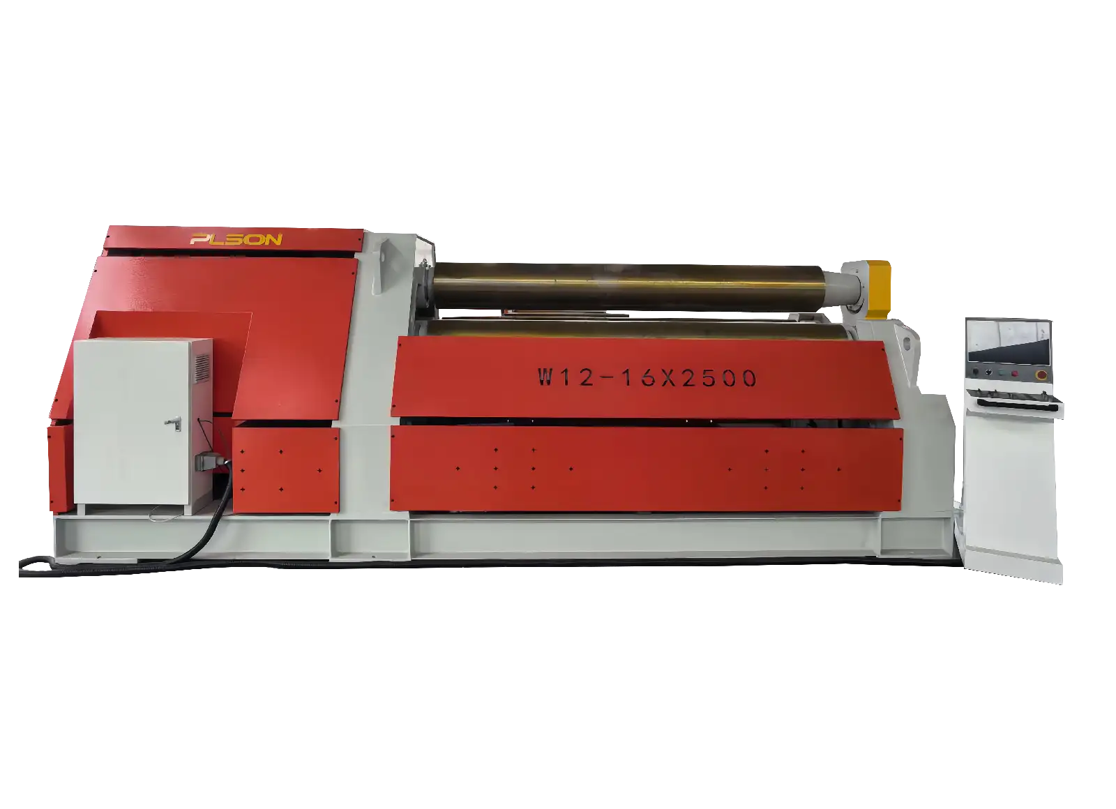
Main Composition of the Equipment
– Upper roll section (upper roll, main drive device for upper roll, driving side bearing body, tilting balance device)
– Lower roll section (two lower rolls, auxiliary drive device for lower roll, horizontal movement device, material aligning device)
– Frame section (base, left and right frames, upper roll drive cylinder)
– Tilting section (upper roll tilting side bearing body, tilting cylinder)
– Cone rolling device
– Hydraulic system (hydraulic pump station system, valve group)
– Electrical control section, high-voltage section, digital display section (PLC control system), control console
– Lubrication system
Structural Features of the Equipment
1. The machine consists of a base, upper roll, lower roll, left and right frames, main drive system, auxiliary drive system, hydraulic system, electrical control system, etc. The base and frames use welded structures, with strict welding quality requirements and aging treatment to ensure the machine has sufficient strength and rigidity under working loads.
2. Working Part
The upper roll is installed in two bearing bodies, which are embedded in the inner sides of the frames. It is driven by cylinders at both ends to move up and down. Both ends of the upper roll use low-speed, heavy-load self-aligning roller bearings. The lifting displacement of the upper roll is digitally displayed, and the work roll parallelism or tilt can be adjusted according to the digital display. Its synchronization accuracy is ±0.2mm. A tilting cylinder is installed on the tilting side of the upper roll for easy material handling. A balance mechanism is installed at the rear of the upper roll. When support is lost on the tilting side, the upper roll remains horizontal.
The two lower rolls are installed inside the upper roll frame, supported by the lower roll frame, using low-speed, heavy-load self-aligning roller bearings. The two lower rolls move horizontally simultaneously under cylinder drive. The horizontal movement is digitally displayed, and the lower work roll parallelism can be adjusted according to the display. The synchronization accuracy is ±0.2mm, and they can automatically return to the center. The material aligning device is installed on one side of the lower roll and is cylinder-driven. The cone rolling device is installed at the left end of the upper roll and moves up and down with it.
3. Main Drive System
All three work rolls of the machine are driven rolls. The upper roll is the main drive roll, capable of handling the maximum load. The two lower rolls are auxiliary drive rolls, used to feed material and prevent slipping when rolling thin plates. The linear speed of the upper and lower rolls is matched automatically by the hydraulic system during plate rolling.
The upper work roll is driven by a hydraulic motor through a planetary reducer. The lower work rolls are driven by hydraulic motors through first-stage gears. All three rolls have brakes to ensure accurate positioning during rolling. The system runs smoothly, making rolling flexible and reliable.
4. Hydraulic System
The lifting of the upper roll, horizontal movement of the lower rolls, rotation of upper and lower rolls, tilting and resetting of the side bearing body, and operation of the material aligning device are all powered by the hydraulic system.
The main components of the hydraulic system, including the oil pump, motor, various valve assemblies, and seals, are all selected from well-known domestic brands, ensuring stable performance and reliable quality. The system piping is neatly arranged with no leaks.
5. Electrical Control System
(1) Structural Composition:
All mechanical actions are centrally controlled by the electrically controlled NC system, with button operations.
A. Digital S System: Uses high-precision sensors and digital displays produced by the domestic Optoelectronics Research Institute.
B. NC Electrical System: Uses OMRON industrial PLCs and color touch LCD screens, along with the corresponding input/output modules. This configuration has proven over long-term usage with various users to have strong anti-interference capability, long service life, vibration resistance, and stable operation.
Sensors use high-precision 11-bit absolute optical encoders to ensure position accuracy and monitor the position of each roller. Major components in the high-voltage part are selected from high-performance domestic and foreign products, featuring long lifespan and long fault-free operation time.
(2) Main Technical Specifications of the System
The system operates at 380V 50Hz, with a display precision of 0.1mm.
When controlling the upper and lower work rollers synchronously with the NC system, the synchronization accuracy is 0.2mm.
(3) Control System Functions
A. The NC system can display various real-time data and rolling sheet information:
Real-time display of the absolute position of both ends of the upper roller; real-time display of the absolute position of both ends of the lower roller.
B. The NC system has the following intelligent functions:
Programmable human-machine interface for setting and input
Fault self-diagnosis display and intelligent identification of operational errors
Logic monitoring and protection of various parts of the machine tool
Soft and hard limit protection for all moving parts
Automatic mid-position return function for the lower roller
Power-off memory function: If there’s a sudden power outage during operation or after the rolling is finished and the machine is powered off for some reason, the PLC system will track the roller position accurately when power is restored, showing the actual position.
Safety protection function: In case of emergencies, operators can conveniently and promptly shut down the equipment and system to ensure both equipment and personal safety.
If you want to watch the video, please click YouTube.