
The Four Operating States and Four “Points” of a Press Brake
Description of Press Brake Operating States
For beginners using a press brake, how does the entire bending process of a workpiece unfold?
Let me now introduce the four operating states of a press brake and the four important “points”:
Four States: Rapid Descent, Work Feed (Slow Descent), Unloading, and Return Stroke
Four “Points”: Upper Dead Center, Lower Dead Center, Clamping Point, and Speed Change Point
01 Rapid Descent Mode
The process in which the upper beam rapidly descends to the speed change point is called rapid descent. While rapid descent does not guarantee precise positioning of the upper beam, the high descent speed effectively improves the overall bending efficiency.
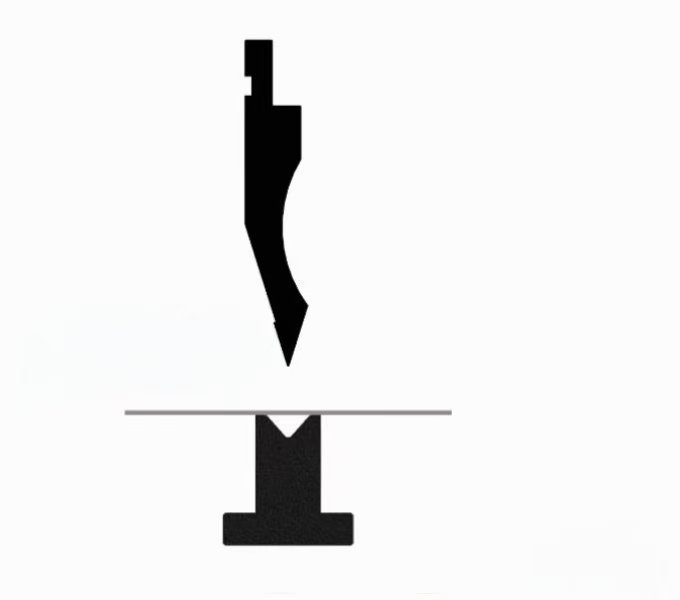
02 Working Feed (Slow Descent) Mode
The process in which the upper beam moves from the speed change point to the set lower dead center position (bending forming position) is called the working feed; that is, the process in which pressure is built up in the upper chamber of the hydraulic cylinder to bend the workpiece. At this time, the lower beam’s descent speed is 0–10 mm/s. The proportional directional control valve can precisely adjust the upper beam’s speed and position, effectively ensuring the accuracy of the upper beam’s arrival at the lower dead center position and guaranteeing the workpiece’s forming angle.
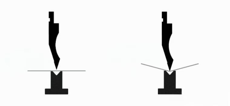
03 Unloading Phase
The upper beam moves slowly upward from the lower dead center position to the set distance; this is referred to as unloading. During unloading, the pressure in the upper chamber of the hydraulic cylinder is released, while pressure is built up in the lower chamber to counteract the upper beam’s own weight, allowing it to rise slowly.
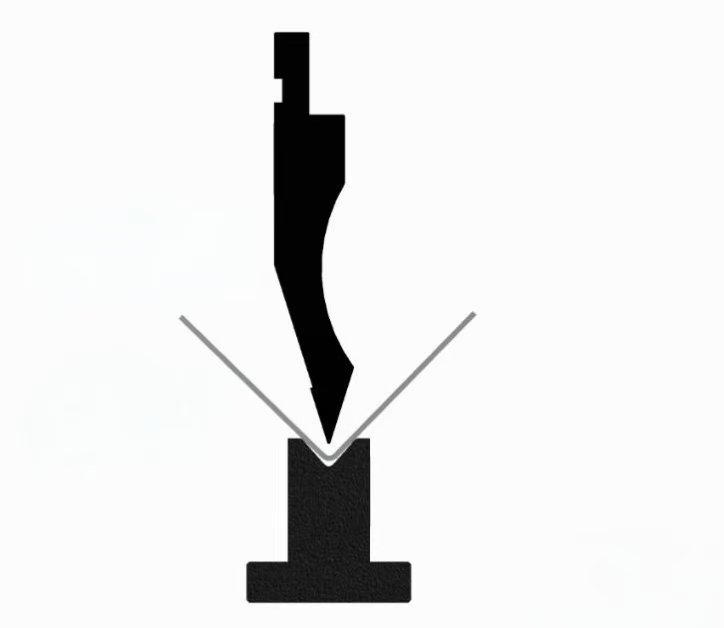
04 Return Stroke
The process in which the upper beam moves rapidly upward to the preset top dead center position is called the return stroke. Throughout the return stroke, the press brake is in a state of overcoming the upper beam’s own weight while the upper beam moves rapidly; therefore, the pressure in the hydraulic circuit is relatively high.
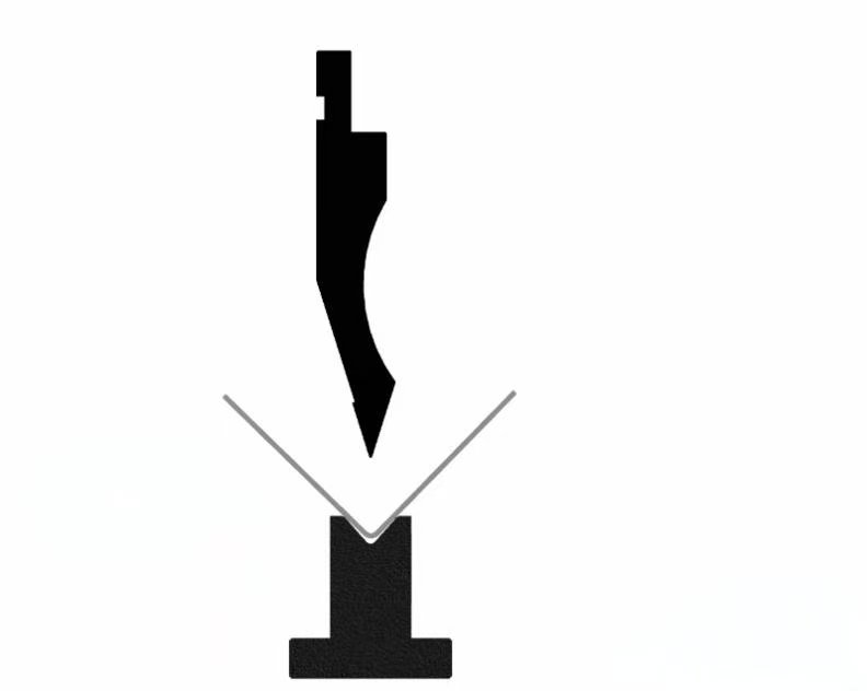
05 Top Dead Center
▪ When the cylinder piston moves to the uppermost limit of its travel path—that is, when the upper beam reaches its highest point—this is referred to as the maximum top dead center.
▪ After the bending cycle ends, the upper beam returns to the position set by the CNC system; this is referred to as the upper dead center.
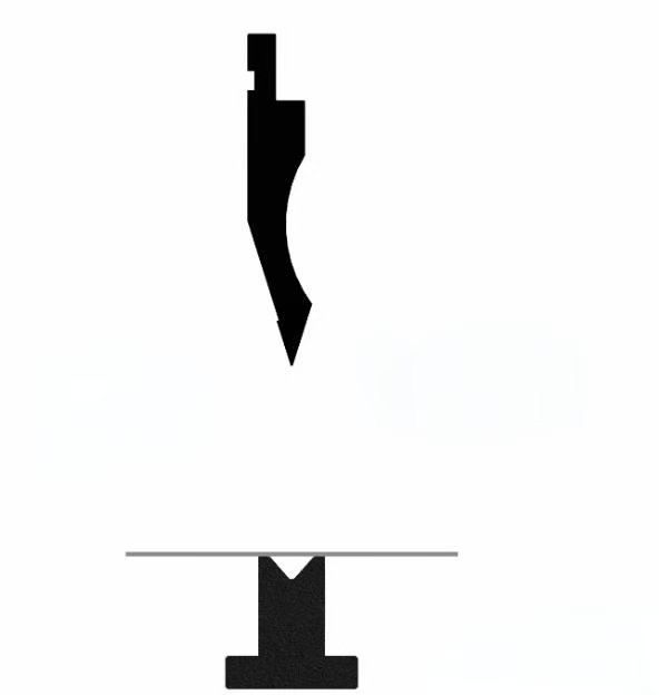
06 Lower Dead Center
When the cylinder piston moves to the lowest limit of its travel path—that is, when the upper beam reaches its lowest point—this is referred to as the maximum lower dead center.
When the upper beam moves to the bending position set by the CNC system—that is, the forming position for the workpiece’s bending angle—this is referred to as the lower dead center.
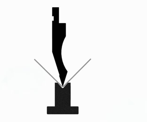
07 Clamping Point
The position where the upper die contacts the workpiece placed on the lower die is referred to as the clamping point; at this point, the sheet metal has not yet undergone deformation and is held in a clamped state, preventing movement. The introduction of the clamping point is commonly used in applications involving rear stop auxiliary retraction or robotic bending.
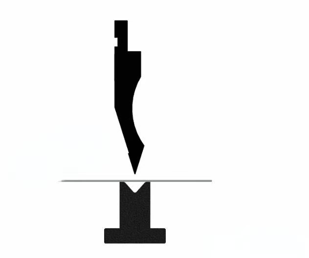
08 Speed Change Point
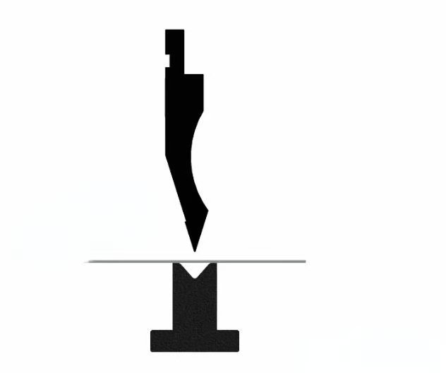
The position where the upper beam’s rapid descent ends and transitions to slow descent (work feed mode) is referred to as the speed change point.
If you want to watch more YouTube
For more press brakes, click here:https://plsoncnc.com/product-category/press-brake/