The Structure of Press Brake Components That Beginners Need to Know
A press brake is a machine used to bend thin sheets of metal into various shapes as required; it is an essential piece of equipment for bending workpieces in the sheet metal industry. A press brake consists of the worktable, the ram, the backgauge, the hydraulic cylinder, and other components. Below, we will provide a detailed introduction to the names and functions of each press brake component that beginners need to know.
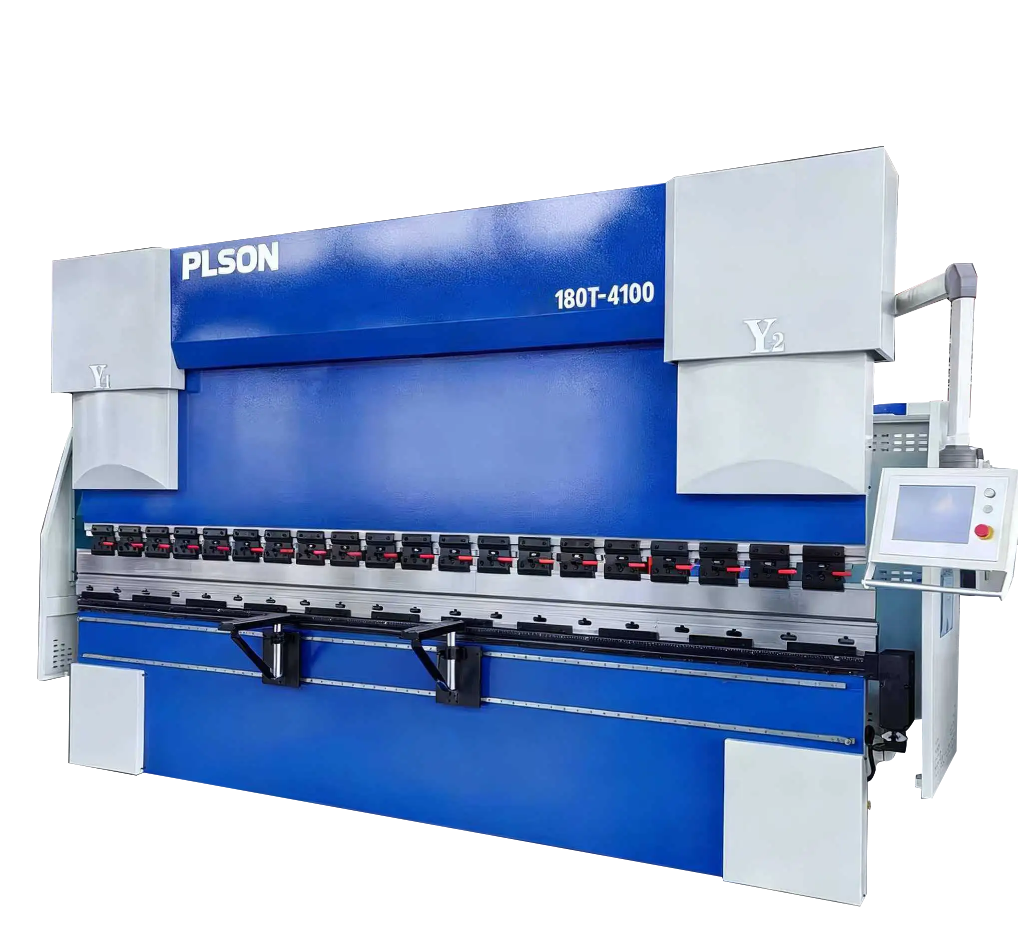
1. Front View of an Electro-Hydraulic Servo CNC Press Brake
1.1 Hydraulic Cylinder
A hydraulic cylinder is a hydraulic actuator that converts hydraulic energy into mechanical energy, performing linear reciprocating motion. Its structure is relatively simple, and it operates very reliably. A hydraulic cylinder basically consists of a cylinder barrel, cylinder head, piston, piston rod, sealing devices, cushioning devices, and venting devices. Its input parameters are fluid flow rate and pressure, and its outputs are linear motion speed and force. It is mounted on both sides of the press brake and drives the ram to move up and down in a reciprocating motion.
1.2 Slider
The slider is a die component that, during the die opening operation, slides perpendicular to—or at a certain angle to—the direction of die opening and closing. It drives the upper die to move in a reciprocating linear motion relative to the lower die, thereby bending the sheet metal to form a specific bend angle (or arc). The slider’s motion consists of four stages: startup and return to zero, rapid drive, working stroke, and slider return. Together with the hydraulic cylinder, mechanical stops, and fine-adjustment mechanism, it forms the slider assembly. Hydraulic pressure drives the piston (rod) to move up and down, while the mechanical stops are controlled and adjusted by the CNC system.
1.3 Quick-Clamp
The quick-clamp is a device on the press brake for rapidly clamping and securing the upper die. Mounted on the press brake’s ram, it is used to quickly clamp, secure, and remove the upper die. The quick-clamp includes a clamping base and a front pressure plate assembly, which can adjust the die to ensure even force distribution, prevent damage to the ram, and reliably maintain the machining accuracy of the workpiece.
1.4 Front Support
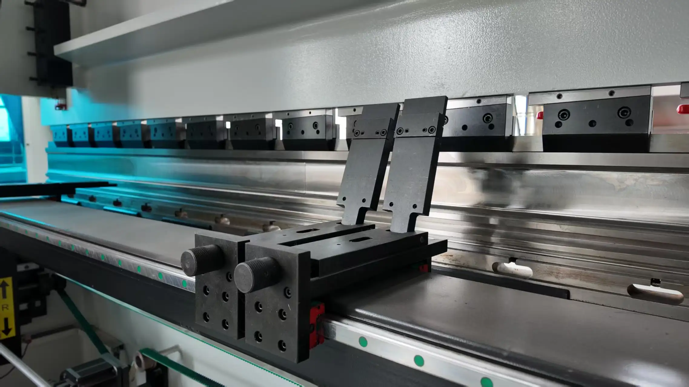
The front support is a device used to support the sheet metal to be bent; it is vertically adjustable and features guide rails that allow for automatic movement. Using the front support to hold the material is safer and more stable than manual handling, ensuring better bending results.
1.5 Worktable
The worktable is one of the three major components of a press brake (left and right hydraulic cylinders, worktable, and ram). It consists of a base and a clamping plate and is operated via a control panel, which drives the motor to move the stop frame back and forth, with the travel distance controlled by the CNC system. When selecting a worktable, one should prioritize a shorter model while ensuring it meets the requirements of the machining task.
1.6 Suspension Arm
The suspension arm is used to hang or support small control cabinets and can rotate in all directions. It has a high load-bearing capacity, and its structure is robust and stable, typically made from high-quality die-cast aluminum alloy.
1.7 Operator Control Panel
The operator control panel houses the press brake’s CNC system, which serves as the “brain” of the machine. Operators input processing instructions—comprising text, numbers, symbols, and graphics—to direct the press brake in executing the machining program. It can store multiple programs and is equipped with interface circuits and servo drive units.
1.8 Dies
Dies are tools used for stamping and forming sheet metal, as well as for separation. Under the pressure of the press brake, they shape the workpiece into the specified dimensions and form. Dies are generally divided into upper dies, lower dies, intermediate plates, guide rails, lower die bases, and shims. The installation and removal of dies must comply with safety regulations, and selection must adhere to the processing parameters of both the machine and the dies to ensure they are compatible.
1.9 Electrical Cabinet
The electrical cabinet is a compact, low-voltage distribution panel that houses the press brake’s electrical wiring, measuring instruments, switches, and related equipment within a metal enclosure. It is typically mounted on the side of the press brake, featuring a compact design, simple operation, and a high safety factor.
1.10 Deflection Compensation
Deflection compensation is used to compensate for the deflection deformation of the ram in order to ensure the precision of the workpiece. The functions of deflection compensation include angle compensation, length compensation, and clearance error compensation. Compensation methods include hydraulic compensation and mechanical compensation. Mechanical compensation has multiple compensation points, which better ensures that the bending results meet expectations and offers relatively more durable operational stability.
1.11 Foot Pedal
The foot pedal is one of the four main components (operator, equipment, system, foot pedal) that control the operation of the press brake. It integrates emergency stop, cycle, and single-cycle remote control functions. The foot control allows for free control of the stopper’s left-right movement, machine start/stop, and integration with machine tool controls. Additionally, it can be equipped with a Wi-Fi module to enable network connectivity, providing seamless monitoring and management across the entire facility and simplifying administration.
2. Rear Structure of an Electro-Hydraulic Servo CNC Press Brake
2.1 Motor
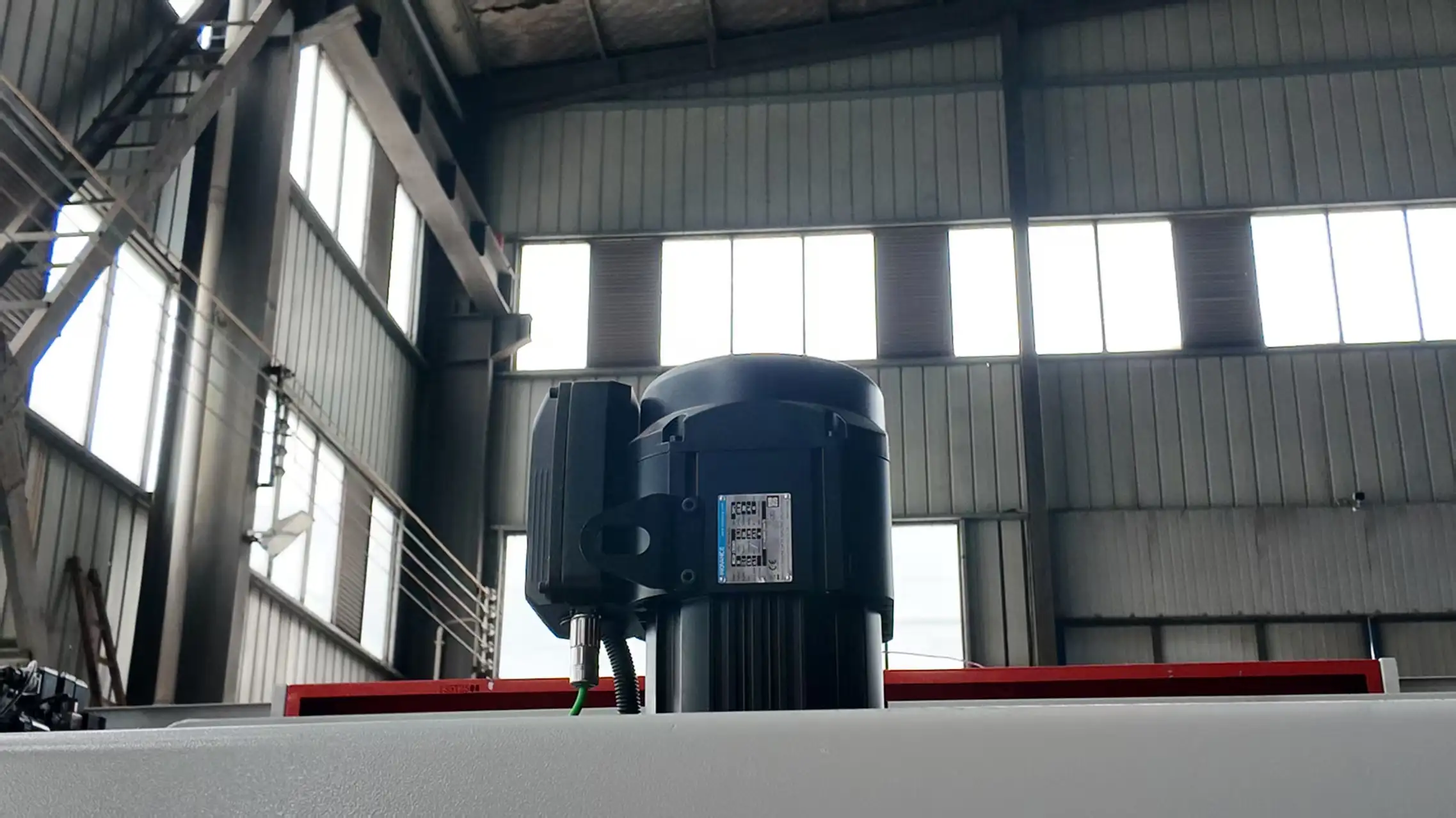
A servo motor is a motor that controls the movement of mechanical components in a servo system; it is a type of auxiliary motor with an indirect speed-variation mechanism. It can control speed with high positional accuracy and converts voltage signals into torque and rotational speed to drive the controlled object. Servo motors are characterized by a small electromechanical time constant and high linearity.
2.2 Stop Fingers
Stop fingers are components that display the dimensions of the workpiece when the front and rear stops are moved. They move smoothly along linear guides and can be adjusted up and down, making them convenient, efficient, and easy to control. Press brakes typically have multiple stop fingers, with the number configured according to actual needs. They operate via point contact, which helps mitigate issues with insufficient sheet metal straightness and enables the bending of sheet metal parts of varying lengths.
2.3 Rear Stop
The stop mechanism uses motor drive, with a chain drive moving the lead screw synchronously; the CNC system controls the stop dimensions. The angles of the front and rear stops can be linked, allowing for combined use of both stops in unison. The rear stop allows for flexible bending of small parts, while the front stop provides excellent forming results. With dual-drive front and rear stop mechanisms, the rear stop provides more accurate positioning, while the front stop ensures precise forming dimensions. When used in combination, they enable the bending of many irregularly shaped products. The integrated height control of the front and rear stops facilitates material feeding and minimizes errors.