
What Are the Accessories and Components of a Hydraulic Shearing Machine?
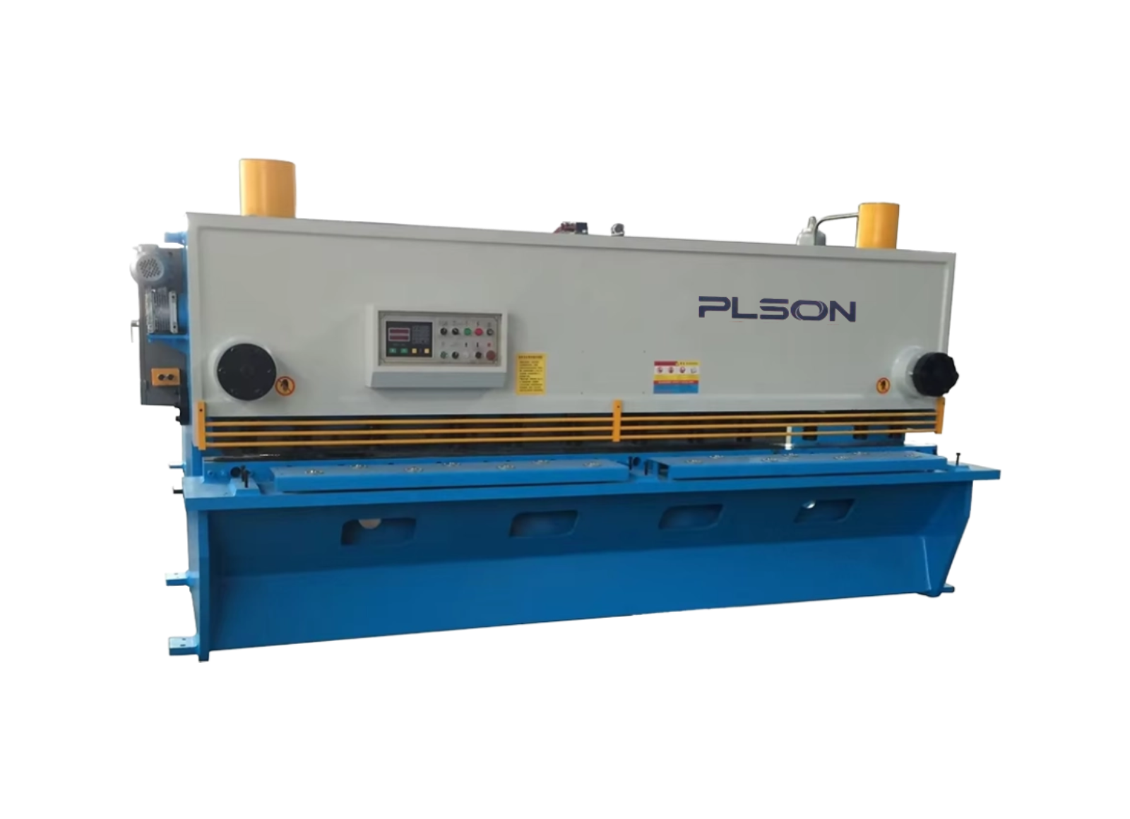
A hydraulic shearing machine operates through the coordinated interaction of various parts and components. The accessories can be classified into the following categories:
1. Electrical System Components
The electrical components of a hydraulic shearing machine generally include: various buttons, indicator lights, contactors for control, transformers, switches, motors, and more.
2. Hydraulic System Components
The hydraulic system accessories typically consist of: oil pumps, valves of various specifications, pressure gauges and their switches, liquid level gauges, oil circuit pipes and fittings, sealing rings, and more.
3. Mechanical Components
Other mechanical accessories of the hydraulic shearing machine include: blades, bearings, blade holders, bolts of various models and specifications, gears, polished rods, and more.
Tip for New Buyers: When receiving your hydraulic shearing machine, always check the completeness of all accessories against the checklist provided in the manual. Though these parts may be small, each one is essential. Identifying any missing components early allows you to put the machine into production sooner.
CNC Development Technology and Basic Composition of Shearing Machines
With the advancement of science and technology, the CNC manufacturing technology for shearing machines has undergone profound changes.
As the market demand for product diversification has grown stronger, the proportion of multi-variety, small-to-medium batch production has increased significantly. Traditional conventional machining equipment can no longer meet the requirements for high efficiency, high quality, and diversified processing.
Basic Composition of a CNC Shearing Machine
A CNC shearing machine consists of the following fundamental components:
The machining program can be written manually by operators. For more complex machining requirements, programs can be created through computer-aided drafting (CAD) and then converted into machining programs. Program input can be performed manually through the CNC system’s panel, transmitted via cable through the computer’s communication port, or transferred using a computer USB interface.
[Contact Our Engineers →] 📧 eric@plsonmachine.com 🏭 Haian Industry Park, Jiangsu Province, China