
The Bending Cycle of a CNC Press Brake: 4 States and 4 Key Points
Posted by PLSON Engineering Team
Introduction
A CNC press brake is a modern sheet metal forming machine that uses computer numerical control to bend metal plate into shape with high precision and high efficiency. It drives the ram (also called the upper beam) up and down using a hydraulic or an electric servo system. The ram carries the upper die, and together with the lower die — normally a block with a V-groove fixed on the machine table — it applies a controlled force to the metal plate placed between them, so that the plate deforms to the programmed angle and shape.
For anyone new to press brakes, the first question is usually a practical one: what actually happens during one complete bending cycle?
The answer is built from two groups of terms: four motion states and four key points. This article explains each one in order, then shows how they fit together into a single cycle.
Safety first: A press brake closes under high force, and the tooling area is where hands and fingers are most often injured. Never place any part of the body between the punch and the die, and never reach into the tooling area or the back gauge area while the machine is running. Keep the light curtains, guards and two-hand controls in working order and never bypass them to speed up a job. Before inspecting the dies, the ram, or the hydraulic system, stop the machine, isolate the main power, and support the ram so it cannot descend under gravity. Only trained and authorized personnel should set dies or change machine parameters.
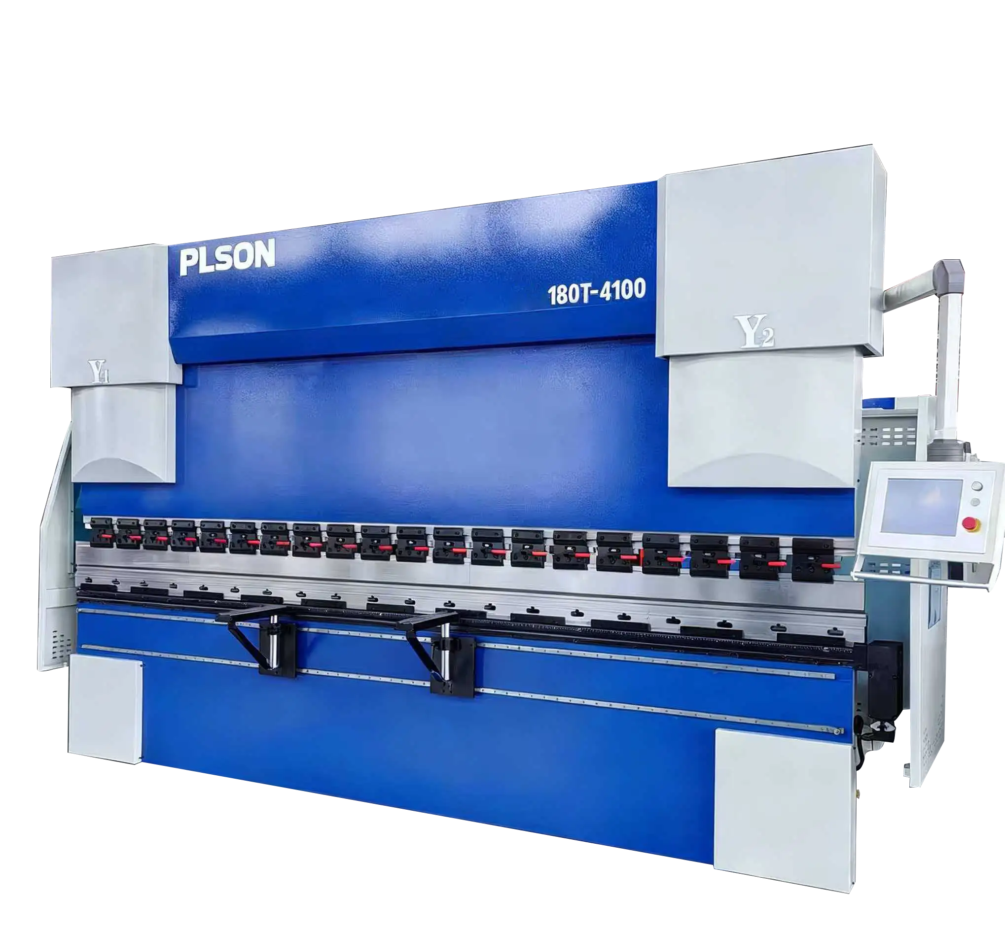
Terminology: Ram, Upper Die, Lower Die
Beginners often find the cycle confusing mainly because three different components are described by similar words. It helps to separate them before going further.
So when we say “the ram descends”, it is the ram carrying the upper die that moves. Keeping that distinction clear makes the four states and four points easy to follow.
Why the Cycle Is Worth Understanding
The bending cycle is not just theory — every parameter the operator sets is a setting on some part of this cycle.
The Four Motion States
One bending cycle consists of four states, in this order.
1. Fast descent
The upper beam descends rapidly and travels to the changeover point. This movement is called fast descent.
Fast descent cannot guarantee accurate positioning of the upper beam. Its purpose is different: the descending speed is high, which effectively shortens the total time of the bending stroke and therefore improves bending efficiency. In other words, fast descent is a productivity feature, not an accuracy feature — which is exactly why it is confined to the part of the stroke where no bending is taking place.
2. Slow descent (working stroke)
The movement of the upper beam from the changeover point to the set bottom dead centre position — the bending position — is called slow descent, or the working stroke.
This is the stage in which the upper chamber of the hydraulic cylinder builds pressure and bends the workpiece. During this stage the descending speed of the upper beam is 0 to 10 mm/s. A proportional directional valve adjusts the speed and the position of the upper beam accurately, which is what guarantees the accuracy with which the beam reaches bottom dead centre — and therefore the forming angle of the workpiece.
Two things are happening in this state at the same time, and it is worth separating them:
- Position control determines how deep the punch goes, which sets the angle.
- Speed control determines how gently it gets there, which sets the surface quality and the load on the tooling.
The reason the speed is reduced to such a low value is that at the moment of contact the machine is working against the full bending resistance of the material. Approaching at high speed would produce a shock load, poor angle control, and marking on the plate surface.
3. Decompression
The upper beam moves slowly upward from the bottom dead centre position to a set distance. This is called decompression.
During decompression, the pressure that was built up in the upper chamber of the cylinder is released, and the lower chamber builds pressure to overcome the self-weight of the upper beam, so that the beam rises slowly.
Why this state exists: after the bend is formed, the material is under a large elastic load. If the ram simply reversed at full pressure, that stored energy would be released suddenly — producing a shock in the hydraulic system, noise, and a risk of the plate being marked or displaced. Decompression releases the pressure in a controlled way, letting the material recover gradually. It is a short movement, but it is one of the most important settings for surface quality and for the life of the hydraulic components.
4. Return
The movement of the upper beam rapidly upward to the set top dead centre position is called return.
Throughout the return the machine is overcoming the self-weight of the upper beam while moving it quickly, so the pressure in the hydraulic circuit is relatively high. That is normal and is why the return stroke is where the hydraulic system is under continuous load.
The Four Key Points
The four states are delimited by four points, which the control system uses to switch between them.
5. Top dead centre
When the piston of the hydraulic cylinder moves to the uppermost limit of its travel — that is, when the upper beam reaches its highest point — this is called the maximum top dead centre.
After the bending cycle ends, the upper beam returns to the position set in the CNC system. That position is called the top dead centre (as used in the cycle). The distinction matters in practice: the mechanical maximum is the physical limit of the machine, while the programmed top dead centre is a parameter. A higher programmed value gives a longer return stroke and a longer cycle time; a lower value shortens the cycle but must still leave enough clearance to remove and reposition the part safely.
6. Bottom dead centre
When the piston of the hydraulic cylinder moves to the lowermost limit of its travel — that is, when the upper beam reaches its lowest point — this is called the maximum bottom dead centre.
When the upper beam moves to the bending position set in the CNC system — the position at which the workpiece angle is formed — this is called the bottom dead centre (as used in the cycle). This is the single most important setting for the bend angle: the depth to which the punch enters the die determines the angle, and small errors in this position show up directly as angle errors on the part. This is also why the slow descent speed, the machine’s rigidity, and the accuracy of the position measurement all matter so much in this state.
A practical note for beginners: because the material springs back after the load is removed, the programmed bottom dead centre is normally not the same as the theoretical depth for the required angle. The value must be established for the material and thickness being processed.
7. Clamping point
The position at which the upper die touches the workpiece placed on the lower die is called the clamping point.
At this moment the plate has not yet deformed, and it is in a clamped state in which it cannot move. Signals at the clamping point are mainly used for two purposes: to let the back gauge fingers retract and clear the workpiece as the bend lifts it, and to coordinate the movements in robotic bending, where the robot must know the exact moment the part becomes fixed. In other words, the clamping point is what makes automation possible — it is the point at which the machine, rather than the operator, knows that the part is no longer free to move.
8. Changeover point
The position at which fast descent of the upper beam ends and slow descent (the working stroke) begins is called the changeover point.
Setting this point correctly is a compromise. If it is set too high, the machine spends unnecessary time creeping down slowly and the cycle becomes slow. If it is set too low, the ram reaches the material at high speed, which produces a shock load, poor angle accuracy, and a risk of marking. The correct value is as low as possible while still allowing the machine to decelerate fully before contact.
One Complete Cycle, Step by Step
Putting the states and points together gives the whole loop.
The cycle then repeats for the next bend. A part that requires four bends simply runs this loop four times, which is why consistency in each individual cycle determines the consistency of the finished part.
Parameters the Operator Sets on This Cycle
Because the states and points are physical positions and speeds, each of them corresponds to a parameter.
Hydraulic and Electric Servo Press Brakes
The description above follows the hydraulic machine, which is still the most common design: the states are created by controlling the pressure in the upper and lower chambers of the cylinder through proportional valves.
On a full-electric servo press brake, the same four states and four points exist, and the operator programs the same parameters — but the motion is produced by a servo motor driving a ball screw or belt instead of by hydraulic pressure. The practical consequences are worth knowing:
The cycle logic is unchanged. What changes is the mechanism that produces it — and therefore the maintenance requirements and the response characteristics.
Conclusion
A CNC press brake is core process equipment in modern sheet metal manufacturing. It combines digital control, precision mechanical design, and modern material forming theory to deliver a step change in the precision, efficiency, consistency, and flexibility of sheet metal bending.
That capability is built on a cycle that is easy to describe once you separate its two parts:
- Four motion states — fast descent, slow descent (working stroke), decompression, and return.
- Four key points — top dead centre, bottom dead centre, clamping point, and changeover point.
The points define where the states begin and end; the states do the work. Fast descent buys speed, slow descent buys accuracy, decompression buys surface quality and machine life, and the return completes the loop.
For a beginner, the fastest way to make sense of a press brake control is to read the parameters as positions and speeds on this single cycle. Every number on the screen corresponds to something physically happening between the upper die and the lower die.
If you are selecting a press brake, or want to know which parameters matter most for your parts and tooling, contact our engineering team with your material, thickness, and required bend angles.
Contact the PLSON Engineering Team for CNC press brake specifications, tooling selection, and technical support.
[Contact PLSON Engineers →]
📧 Eric@plsonmachine.com
🏭 Haian Industry Park, Jiangsu Province, China